Objective
To explore the distribution of normal stresses in a two-rib beam subjected to uniformly distributed loads applied in the plane of the ribs.
Reference
A.V.Alexandrov, B.Y.Lashchenikov, N.N.Shaposhnikov. Structural mechanics. Thin-walled spatial systems. — Moscow: Stroyizdat, 1983.
Problem statement
A two-rib beam is simply supported by end diaphragms that are perfectly rigid in their plane and perfectly flexible out of their plane. The beam is subjected to uniformly distributed line loads q applied along the ribs in their plan.
To determine the longitudinal normal stress σxi at cross‑sectional points i = 1, 4, 5, and 6 at half‑span (l/2) and quarter‑span (l/4), considering the assumptions adopted in deriving the analytical solution:
1. Bending deformations of the beam components out of their plane are neglected.
2. No transverse displacements in the horizontal plane are assumed at the connections between the ribs and the flange.
3. Differences in stresses between the beam components at the rib-to-flange connections are neglected.
Design model
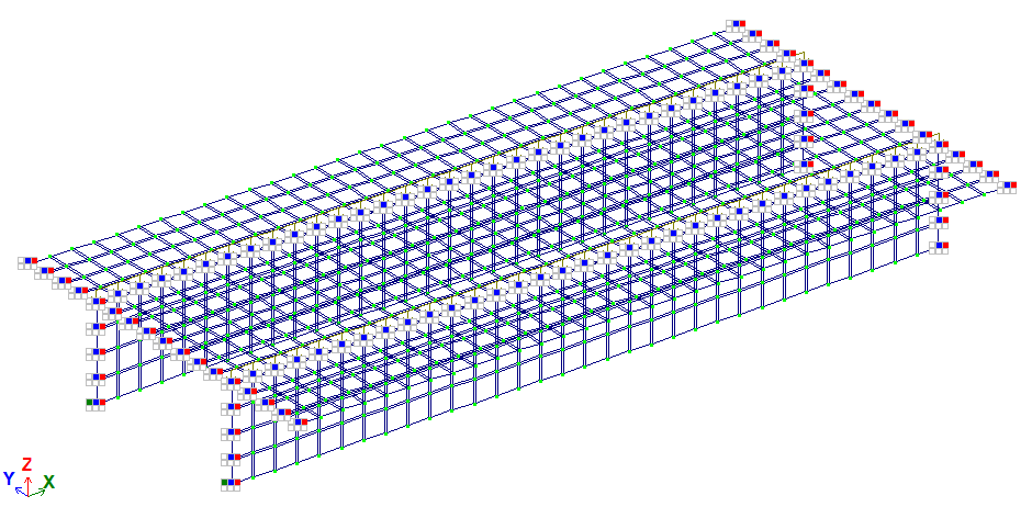
The design model is model type 5; 6 DOF per node. The FE mesh is divided with a step of 0.25 m in the transverse direction of the beam and 0.2453125 m in the longitudinal direction. Internal forces are to be determined along the X-axis of the global coordinate system.
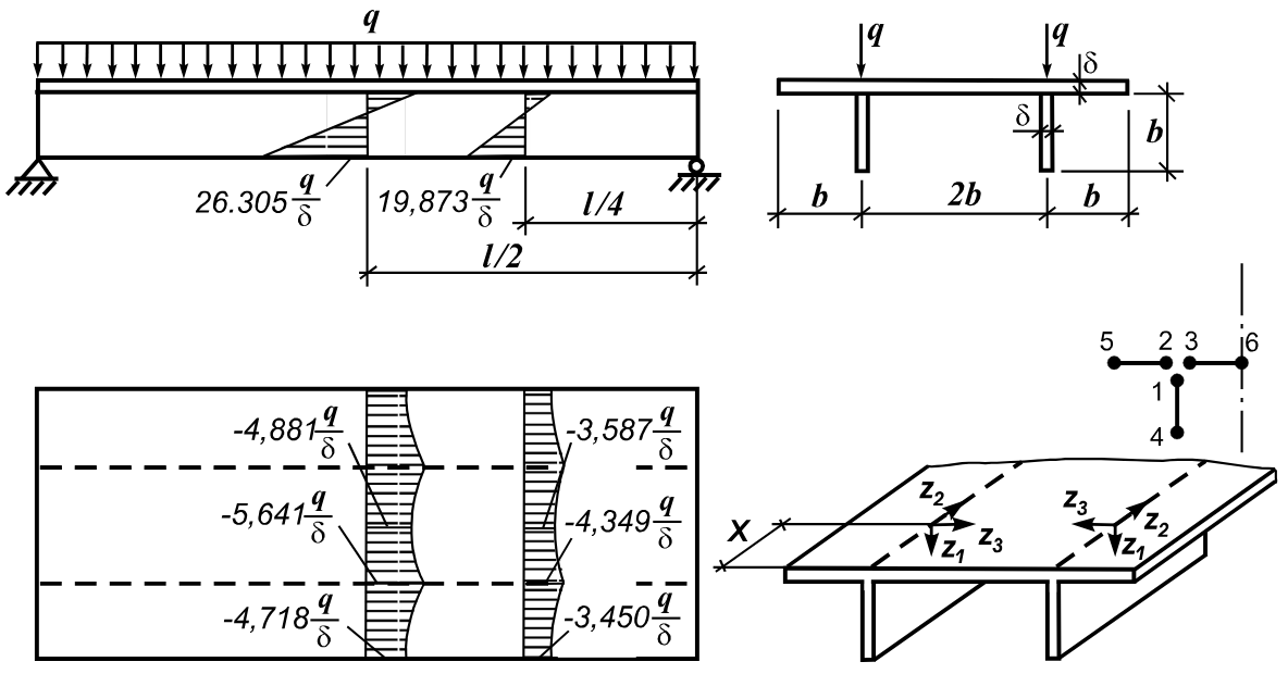
Geometry
Rib and flange thickness δ = 0,1 m
Rib height b = 1 m
Distance between the ribs 2*b = 2 m
Flange width 4*b = 4 m
Beam length l = 7,85*b = 7,85 m
Material properties
Modulus of elasticity Е = 3*107 kPa
Poisson's ratio ν=0,15
Boundary conditions
The boundary conditions are provided by applying restraints:
- in the Y degree of freedom along the ribs;
- in the Y and Z degrees of freedom along the edges parallel to the Y-axis;
- in the X, Y, and Z degrees of freedom at the origin.
Loads
Uniformly distributed line load applied along the ribs q = 10 kN/m.
Note
The problem is solved in 3D formulation (model type 5).
The model is generated with FE type 30 – arbitrary quadrilateral FE of 2D problem (wall-beam).
Nodes: 825. Elements: 768.
Output data
|
|
|
|
Design model
|
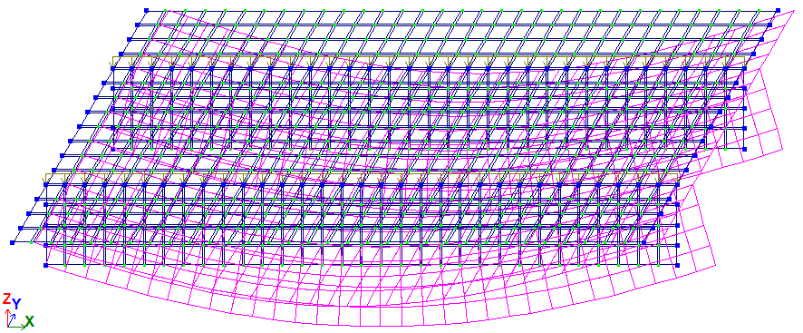
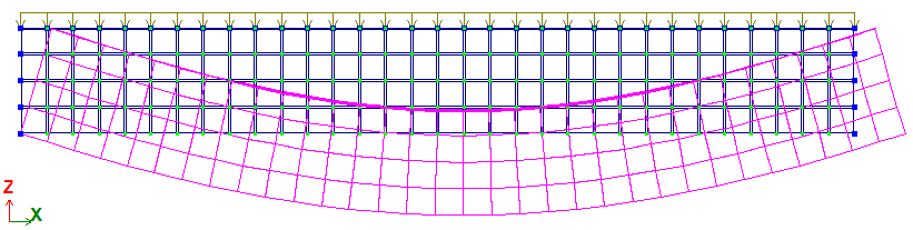
Deformed shape
|
|
|
|
Deformed shape
|
|
|
|
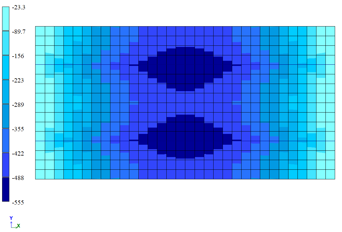
Normal stresses in the beam flange σxi, kN/m2
|
|
|
|
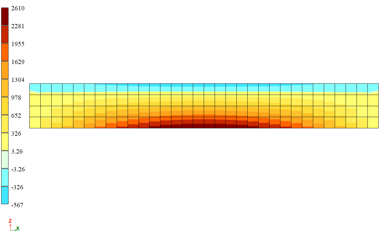
Normal stresses in the beam rib σxi, kN/m2
|
Analytical solution
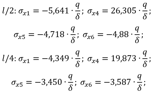
For an analytical solution based on seven harmonics of the unknown generalized displacements, the longitudinal normal stresses σxi (kN/m²) in the beam components at cross-sectional points i = 1, 4, 5, and 6 at half-span (l/2) and quarter-span (l/4) can be calculated using the following formulas:
Comparison of calculation results
Without additional side nodes:
| x,м | l/2 = 3,925 | l/4 = 1,9625 | ||||||
| i | 1 | 4 | 5 | 6 | 1 | 4 | 5 | 6 |
| Theory | -564 | 2631 | -472 | -488 | -435 | 1987 | -345 | -359 |
| LIRA-FEM | -566 | 2607 | -465 | -481 | -437,5 | 1968,5 | -339 | -353 |
| Error, % | 0,35 | 0,91 | 1,48 | 1,43 | 0,57 | 0,93 | 1,74 | 1,67 |
With additional side nodes:
| x,м | l/2 = 3,925 | l/4 = 1,9625 | ||||||
| i | 1 | 4 | 5 | 6 | 1 | 4 | 5 | 6 |
| Теорія | -564 | 2631 | -472 | -488 | -435 | 1987 | -345 | -359 |
| LIRA-FEM | -567 | 2633 | -472 | -488 | -439,5 | 1991,5 | -345 | -359 |
| Похибка, % | 0,53 | 0,08 | 0,00 | 0,00 | 1,03 | 0,23 | 0,00 | 0,00 |
Завантажити приклад
If you find a mistake and want to inform us about it, select the mistake, then hold down the CTRL key and click ENTER.
Comments