Objective
To determine the maximum displacements and bending moments in a square plate simply supported along the perimeter and subjected to a uniformly distributed load p.
Reference
Strength, stability, and vibrations. Handbook in Three Volumes. Volume 1. Edited by I.A.Birger and Y.G.Panovko. — M.: Mashinostroyenie, 1968, pp. 532-535.
Problem statement
A square isotropic plate of constant thickness is simply supported along its perimeter and subjected to a uniformly distributed load p.
To determine: the maximum displacements and the maximum bending moments.
Design model
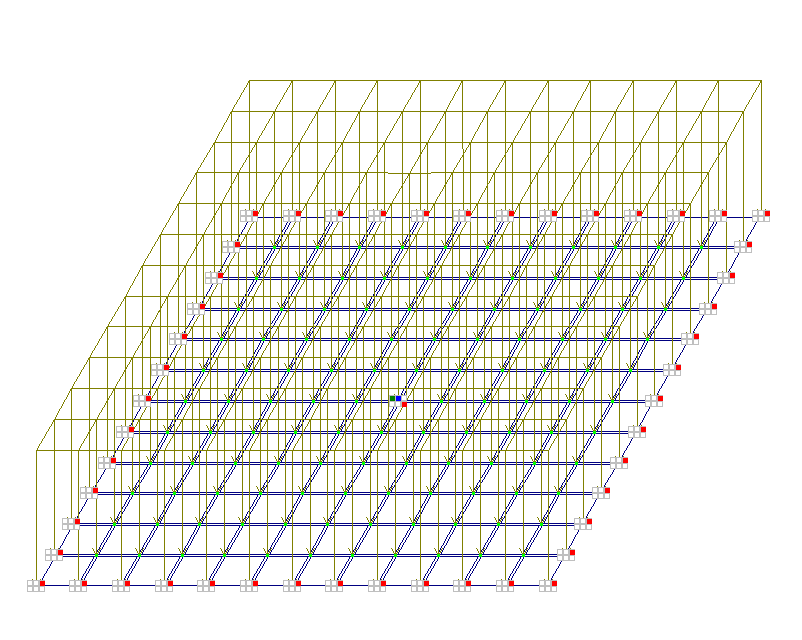
The design model is a beam grillage, slab.
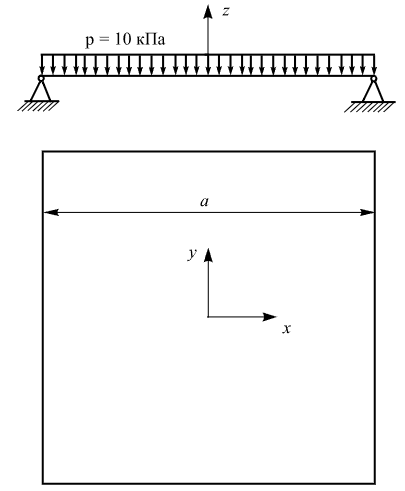
Geometry
Slab side dimension a = 1,5 m
Plate thickness h = 0,01 m
Material properties
Modulus of elasticity Е = 2,0 * 108 kPa
Poisson's ratio ν = 0,3
Boundary conditions
Hinged support of nodes along the contour out of the XOY plane (displacement w = 0).
Restraints are applied in the X, Y, and uZ degrees of freedom directions at the centre of the plate.
Loads
Load p = 10 kPa
Note
The problem is solved in 3D formulation (model type 5).
The model is generated with FE type 19 – quadrilateral FE of slab.
Nodes: 169. Elements: 144.
Output data
|
|
|
Design model
|
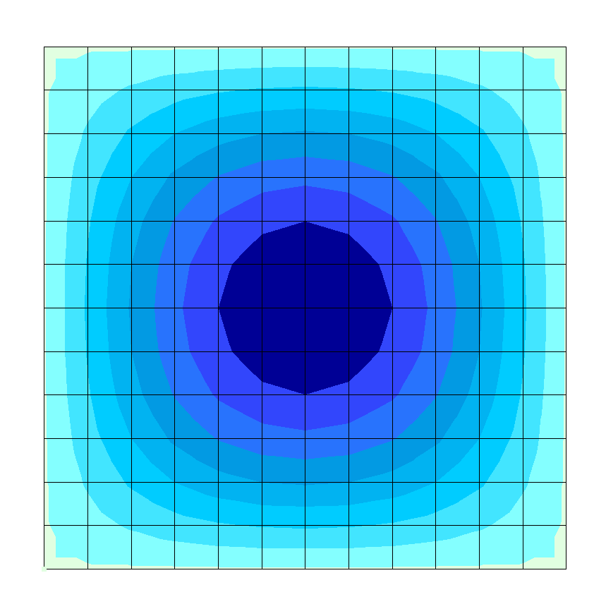
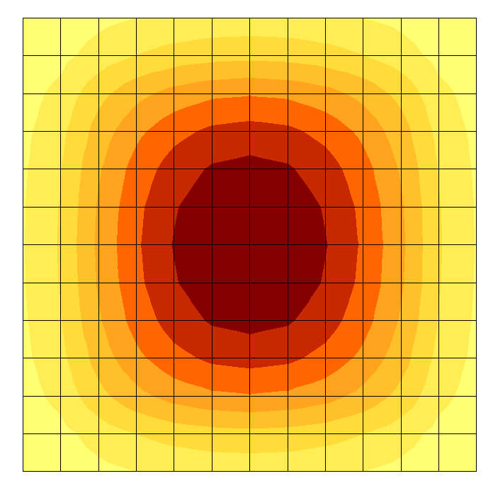
Displacements w, mm
|
|
|
|
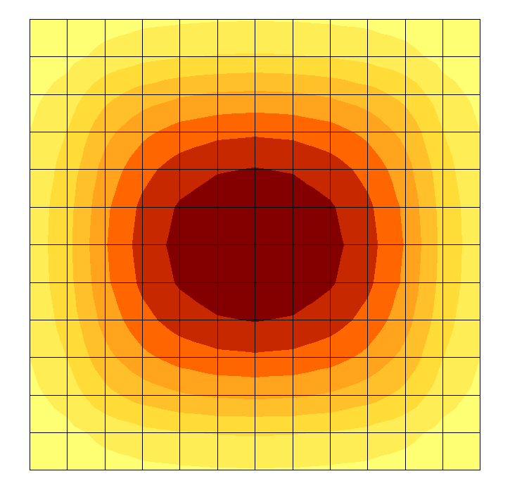
Bending moments Mx, kN*m/m
|
Bending moments My, kN*m/m
|
Analytical solution
In the analytical solution, the displacement w and the bending moments Mx and My at the centre of the plate are calculated using the following formulas:
w = 0,00406*(p*a4)/D, where
D = (E*h3)/(12*(1-ν));
Mx = My = 0,0479*p*a2.
Comparison of calculation results
| Parameter | Theory | LIRA-FEM | Error, % |
| Displacement at plate centre w, mm | -11,22 | -11,23 | 0,09 |
| Bending moment Mx, kN*m/m | 1,078 | 1,065 | 1,2 |
| Bending moment My, kN*m/m | 1,078 | 1,065 | 1,2 |
Download verification test
If you find a mistake and want to inform us about it, select the mistake, then hold down the CTRL key and click ENTER.
Comments