Objective
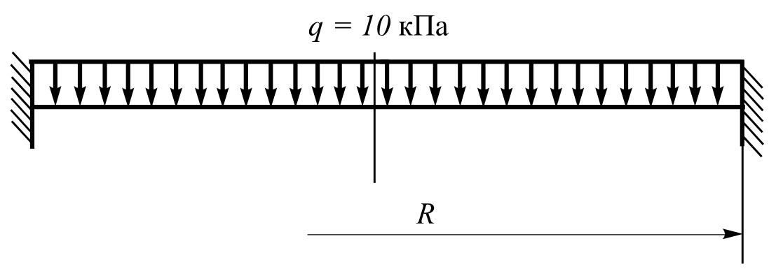
To determine the stress-strain state of a circular plate of constant thickness, clamped at its edges and subjected to a uniformly distributed transverse load.
Reference
S.P.Timoshenko, Plates and shells. — Moscow: OGIZ, Gostekhizdat, 1948.
Problem statement
A circular plate of constant thickness, rigidly clamped at its edges, is subjected to a uniformly distributed transverse load. To determine:
- the deflection Y(G);
- the displacement uX(G);
- the radial bending moment Mx;
- the tangential bending moment My,
along the plate axis and at its outer boundary.
Design model
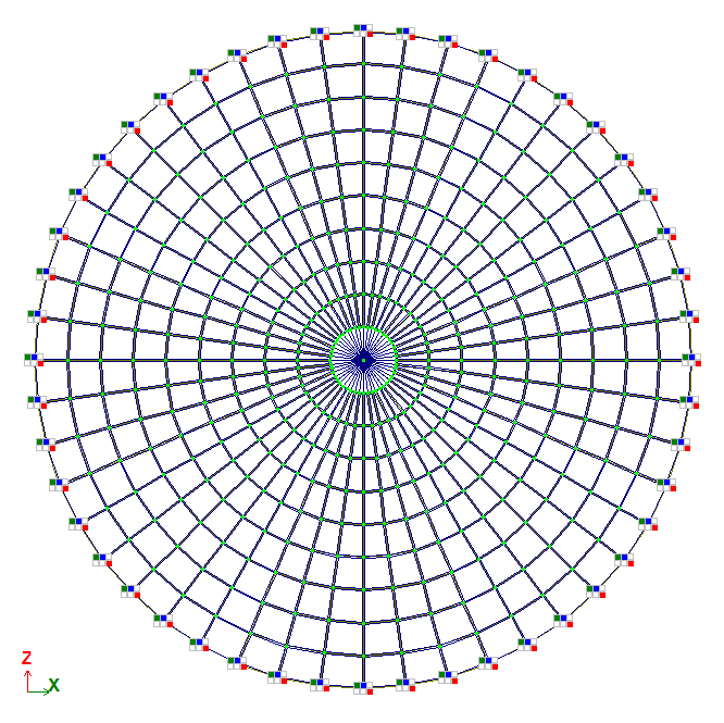
Design model - model type 5, 6 DOF per node. Internal forces are to be determined in the radial‑tangential coordinate system.
The FE mesh is divided:
- in the radial direction from r = 0.00 m to r = 1.2 m with a step of 0.10 m;
- in the tangential direction with a step of 7.5°.
Geometry
Outer radius of the plate R = 1,2 m
Plate thickness h = 2*10-2.
Material properties
Modulus of elasticity Е = 2*108 Pa
Poisson's ratio ν=0,3.
Boundary conditions
The boundary conditions are provided by applying restraints in the Z, uX, and uY degrees of freedom at the nodes along the outer edge of the plate.
Loads
Uniformly distributed transverse load q = 10 kPa.
Note
The problem is solved in 3D formulation (model type 5).
The model is generated with FE type 46 and 47 – arbitrary FEs of thick shell.
Nodes: 481. Elements: 480.
Output data
|
|
|
Design model
|
|
|
|
|
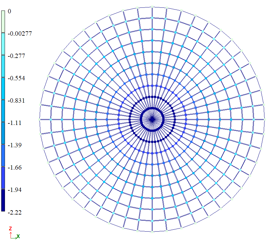
Mosaic plot of displacements along Y(G), mm
|
Mosaic plot of rotations about uX(G), rad*1000
|
|
|
|
|
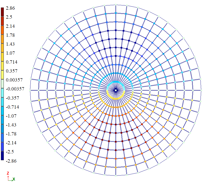
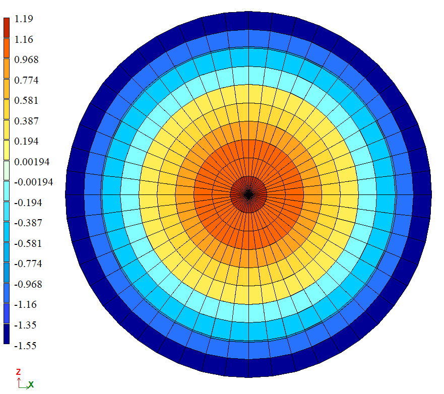
Stress mosaic plot Mx, kN*m/m
|
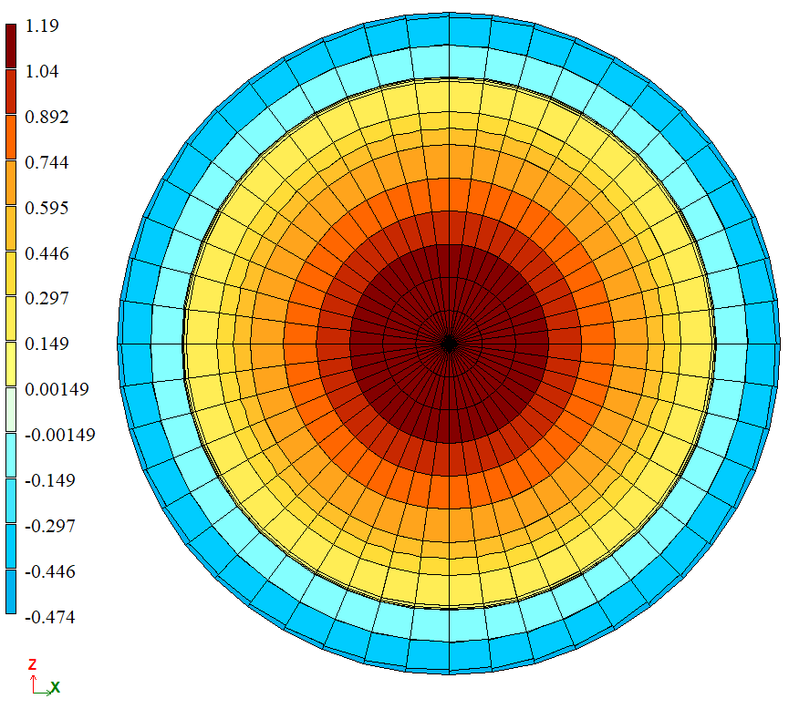
Stress mosaic plot My, kN*m/m
|
Analytical solution
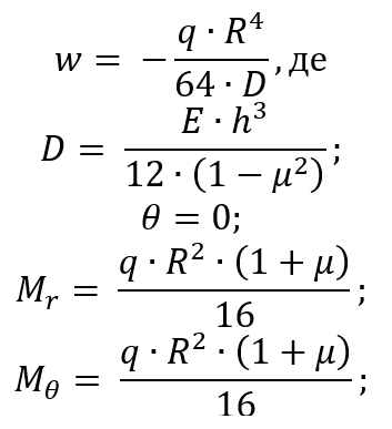
The deflection Y(G), displacement uX(G), and the radial (Mx) and tangential (My) bending moments along the plate axis can be calculated using the following formulas:
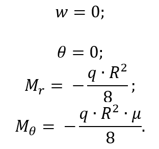
The deflection Y(G), displacement uX(G), and the radial (Mx) and tangential (My) bending moments at the outer edge of the plate can be calculated using the following formulas:
Comparison of calculation results
Without additional side nodes:
| Parameter | Along axis of plate | ||
| Theory | LIRA-FEM | Error, % | |
| Y(G), mm | -2,211 | -2,21 | 0,05 |
| uX(G), rad*1000 | 0,000 | 0,000 | - |
| Mx, kN*m/m | 1,170 | 1,189 | 1,69 |
| My, kN*m/m | 1,170 | 1,189 | 1,69 |
| Parameter | Along the outer contour of the plate | ||
| Theory | LIRA-FEM | Error, % | |
| Y(G), mm | 0,000 | 0,000 | - |
| uX(G), rad*1000 | 0,000 | 0,000 | - |
| Mx, kN*m/m | -1,800 | -1,555 | 13,61 |
| My, kN*m/m | -0,540 | -0,469 | 13,15 |
With additional side nodes:
| Parameter | Along axis of plate | ||
| Theory | LIRA-FEM | Error, % | |
| Y(G), mm | -2,211 | -2,193 | 0,81 |
| uX(G), rad*1000 | 0,000 | 0,000 | - |
| Mx, kN*m/m | 1,170 | 1,165 | 0,43 |
| My, kN*m/m | 1,170 | 1,165 | 0,43 |
| Parameter | Along the outer contour of the plate | ||
| Theory | LIRA-FEM | Error, % | |
| Y(G), mm | 0,000 | 0,000 | - |
| uX(G), rad*1000 | 0,000 | 0,000 | - |
| Mx, kN*m/m | -1,800 | -1,585 | 11,94 |
| My, kN*m/m | -0,540 | -0,482 | 10,74 |
Download verification test
If you find a mistake and want to inform us about it, select the mistake, then hold down the CTRL key and click ENTER.
Comments