Objective
To determine the stress–strain state of a cantilever plate.
Reference
S. Timoshenko, Résistance des matériaux, t. 1, Paris, Librairie Polytechnique Ch. Béranger, 1949.
Problem statement
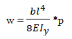
Determine the vertical displacement Z (w) of the free edge of the plate, and the bending moment at the rigid support.
Design model
A rectangular cantilever plate is subjected to a uniformly distributed load q.
|
|
|
|
a |
b |


Geometry
Plate thickness h = 0,005 m;
Cantilever projection l = 1 m;
Relative plate thickness h/l = 0,005;
Plate width b = 0,1 m.
Material properties
Modulus of elasticity Е = 2,1 * 1011 Pa.
Poisson's ratio ν = 0.
Boundary conditions
The left edge of the plate is fully fixed with respect to all degrees of freedom of the slab finite element (Z, uX, uY).
Loads
Load uniformly distributed across the area: q = 1700 Pa.
Note
The problem is solved in a plane formulation (model type 3 – XOY plane).
FE types used: FE 11 – rectangular FE of plate.
FE 11 has three degrees of freedom per node:
– displacement along the global Z-axis,
– rotations about the global X- and Y-axes (uX, uY).
Size of finite elements: 0.01 × 0.01 m.
Number of nodes: 1111. Number of elements: 1000.
Output data

|
|
|
|
Contour plots of vertical displacements Z(w), m
|
Mosaic plot of bending moments Mx, N*m/m
|
, m")

Analytical solution
M = −ql2/2
Comparison of calculation results
Without additional side nodes:
| Point | The unknown | Analytical solution | LIRA-FEM | Error, % |
| x = 1 | Vertical displacement, m | -0,0973 | -0,0972 | 0,1028 |
| x = 0 | Bending moment, N*m/m | -850 | -842,38 | 0,8965 |
With additional side nodes:
| Point | The unknown | Analytical solution | LIRA-FEM | Error, % |
| x = 1 | Vertical displacement, m | -0,0973 | -0,0972 | 0,1028 |
| x = 0 | Bending moment, N*m/m | -850 | -842,36 | 0,8988 |
Download verification test
If you find a mistake and want to inform us about it, select the mistake, then hold down the CTRL key and click ENTER.
Comments