Objective
Combined loading (transverse load and concentrated load) acting in a single plane, neglecting transverse shear deformation. Displacements and internal forces are verified.
Reference
Pisarenko G.S., Yakovlev A.P., Matveev V.V. Handbook of Strength of Materials. Kyiv: Naukova Dumka, 1988.
Problem statement
To determine displacements w, rotation angles θ, shear forces Q and bending moments M.
Design model
A simply supported beam is subjected to a concentrated load P and a uniformly distributed load q.


Geometry
Beam length L = 3 m;
Moment of inertia I = 2,44 * 10-6 m4;
Cross-sectional area F = 14,2 * 10-4 m2;
Geometric dimensions a = b = 1,5 m.
Material properties
Modulus of elasticity Е = 2,0 * 1011 Pa.
Poisson's ratio ν = 0,3.
Loads
Load q = 10 kN/m.
Concentrated load F = -5 kN.
Note
The design model is a plane frame with 10 bar elements of type 2.
Number of nodes in design model: 11.
Output data
|
|
|
|
Transverse displacements, w (mm)
|
Rotation angles, θ (rad*1000)
|
|
|
|
|
Diagram of bending moment, M (kN*m)
|
Diagram of shear force, Q (kN)
|
")
")
")
")
Analytical solution
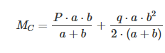
In the analytical solution, the deflection at point C is calculated using the following formula:

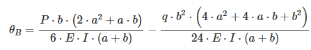
The rotation angle at point B is calculated using the following formula:
The bending moment at point C is calculated using the following formula:
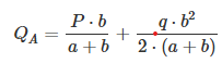
The shear force at point A is calculated using the following formula:
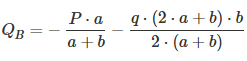
The shear force at point B is calculated using the following formula:
Comparison of calculation results
| Parameter | Analytical solution | LIRA-FEM | Error, % |
| Deflection at point C, mm | -5,043 | -5,043 | 0 |
| Rotation angle at point B, rad*1000 | -7,204 | -7,204 | 0 |
| Bending moment at point C, kN | 1,875 | 1,875 | 0 |
| Shear force at point A, kN | 1,25 | 1,25 | 0 |
| Shear force at point B, kN | -8,75 | -8,75 | 0 |
Download verification test
If you find a mistake and want to inform us about it, select the mistake, then hold down the CTRL key and click ENTER.
Comments