Objective
To analyse a beam fixed at both ends subjected to in-plane loading without considering shear deformation. The maximum transverse deflection and bending moments are verified.
Reference
Pysarenko G.S., Yakovlev A.P., Matveev V.V. Handbook of Strength of Materials. Kyiv: Naukova Dumka, 1988.
Problem statement
To determine the maximum transverse deflection w and the bending moments M.
Design model
A beam fixed at both ends is subjected to a uniformly distributed load q.


Geometry
Beam length L = 3 m.
Moment of inertia I = 2,44 * 10-6 m4.
Cross-sectional area F = 14,2 * 10-4 m2.
Material properties
Modulus of elasticity Е = 2,1 * 1011 Pa.
Poisson's ratio ν = 0,3.
Loads
Uniformly distributed load q= 10 kN/m.
Note
The design model is a plane frame with 10 bar elements of type 2.
Number of nodes in design model: 11.
Output data
")
")
Analytical solution
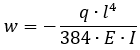
In the analytical solution, the mid-span deflection of the beam is calculated using the following formula ("Handbook of Strength of Materials", p. 352):
The bending moments at the fixed ends are calculated using the following formula:
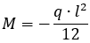
Bending moment at the beam centre:

Comparison of calculation results
| Parameter | Analytical solution | LIRA-FEM | Error, % |
| Transverse displacement at midspan of the beam, mm | -4,32 | -4,32 | 0 |
| Bending moment at midspan of the beam, kN*m | 3,75 | 3,75 | 0 |
| Bending moment at the beam support, kN*m | -7,5 | -7,5 | 0 |
Download verification test
If you find a mistake and want to inform us about it, select the mistake, then hold down the CTRL key and click ENTER.
Comments