Objective
To determine the stress–strain state of a beam fixed at both ends subjected to uniform heating.
Reference
S. P. Timoshenko, Strength of Materials, Vol. 1: Elementary Theory and Problems, Moscow, Nauka, 1965, p. 35.
Problem statement
To determine the normal stresses in the cross-sections of the bars forming the system.
Design model
The system consists of two coaxial horizontal bars with square cross-sections, rigidly connected at a common node and rigidly fixed at the opposite end nodes.
The system is subjected to a temperature change Δt relative to the initial temperature.


Geometry
Length of the left bar L1 = 100 cm
Length of the right bar L2 = 100 cm
Cross-sectional area of the left bar F1 = 1,0 cm
Cross-sectional area of the right bar F2 = 2,0 cm
Material properties
Modulus of elasticity for steel Еs = 2,0 * 106 kg/cm2
Coefficient of linear thermal expansion for steel αs = 1,25 * 10-5 1/ ºC
Loads
Temperature change of the system Δt = 60 ºC
Note
The design model is a plane frame consisting of two elements of type 2.
The boundary conditions are defined by applying restraints in the X, Z, and UY degrees of freedom at the end nodes of the system. The temperature change Δt relative to the initial temperature is applied uniformly along the longitudinal axes of all bar elements.
Number of nodes in design model: 3.
Output data
")
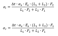
Analytical solution
In the analytical solution, the normal stresses in the cross-sections of the system’s bars are determined by the following formulas:
Comparison of calculation results
| Parameter | Analytical solution | LIRA-FEM | Error, % |
| normal stress σ (left bar), kg/cm2 | -2000 | -2000.0 / (1.0 * 1.0) = -2000.000 | 0 |
| normal stress σ (right bar), kg/cm2 | -1000 | -2000.0 / (1.0 * 2.0) = -1000.000 | 0 |
Download verification test
If you find a mistake and want to inform us about it, select the mistake, then hold down the CTRL key and click ENTER.
Comments