Objective
To determine the deformed state of a simply supported beam (with three stiffness steps) subjected to concentrated loads, neglecting transverse shear deformation. Transverse displacements and rotations are verified.
Reference
Pisarenko G.S., Yakovlev A.P., Matveev V.V. Handbook of Strength of Materials. Kyiv: Naukova Dumka, 1988.
Problem statement
To determine the rotations of the beam cross-sections and the transverse displacements at the points of load application.
Design model
A simply supported stepped beam consisting of three segments with different stiffness properties is subjected to three concentrated loads (P). The beam has a single span and is hinged at both supports.


Geometry
Half-span length of each beam span L = 1 m
Moment of inertia I = 5 * 10-6 m4
Cross-sectional area F = 1 * 10-2 m2
I1 : I2 : I3 = 1 : 2 : 3
F1 : F2 : F3 = 1 : 2 : 3
Material properties
Modulus of elasticity Е = 2,0 * 1011 Pa
Loads
Load q = 10 kN/m
Concentrated load P = 1 kN
Note
The design model is a general-purpose system consisting of 6 bar elements of type 2.
Number of nodes in the design model: 7.
Output data
")
")
Analytical solution
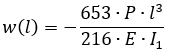
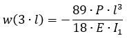
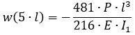
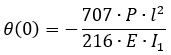
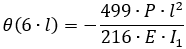
In the analytical solution, the rotations at the support sections and the deflections at the points of application of the concentrated loads are calculated using the following formulas:
|
|
|
|
|
|
Comparison of calculation results
| Parameter | Analytical solution | LIRA-FEM | Error, % |
| Transverse displacements, mm | |||
| w (l) | -3.02 | -3.02 | 0 |
| w (3l) | -4.94 | -4.94 | 0 |
| w (5l) | -2.23 | -2.23 | 0 |
| Rotation angles, θ (rad*1000) | |||
| θ (0) | 3.27 | 3.27 | 0 |
| θ (6l) | -2.31 | -2.31 | 0 |
Download verification test
If you find a mistake and want to inform us about it, select the mistake, then hold down the CTRL key and click ENTER.
Comments