Objective
To analyse bending in the plane of loading under the concentrated load, neglecting transverse shear deformations. The maximum values of transverse displacement w, rotation angle θ, and bending moment M are verified.
Reference
Pisarenko G.S., Yakovlev A.P., Matveev V.V., Handbook of Strength of Materials. Kyiv: Naukova Dumka, 1988, p. 263.
Problem statement
To determine the maximum values of the transverse displacement w, rotation angle θ, and bending moment M.
Design model
A cantilever beam is subjected to a concentrated load P applied at the free end.


Geometry
Length L=3 м.
Moment of inertia of the cross-section I = 2,44 * 10-6 m4;
Material properties
Modulus of elasticity Е = 2,0 * 1011 Pa.
Poisson's ratio ν = 0,3
Loads
Vertical concentrated load: Р = 5 kN.
Note
The design model is a general system consisting of:
– 10 beam elements of type 5;
– 11 nodes.
Output data


")
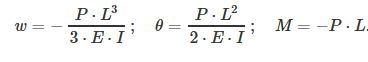
Analytical solution
In the analytical solution, the maximum transverse displacement w, rotation θ, and bending moment M are obtained from the following formulas:
Comparison of calculation results
| Parameter | Analytical solution | LIRA-FEM | Error, % |
| Vertical displacement w, mm | -92,21 | -92,21 | 0 |
| Rotation angle θ, rad | 0,04611 | 46,1 * 10-3 | 0 |
| Bending moment M, kN*m | -15,0 | -15,0 | 0 |
Download verification test
If you find a mistake and want to inform us about it, select the mistake, then hold down the CTRL key and click ENTER.
Comments