- STO 36554501-006-2006 'Regulations to ensure fire resistance and fire durability of RC structures'
- DSTU-N B EN 1992-1-2:2012
The following types of sections may be analysed:
 - rectangular bar
 - T-section (flange at the top)
  - T-section (flange at the bottom)
  - I-section
 - ring
- all types of composite (steel and RC) sections.
Analysis on fire resistance may be carried out either in VISOR-SAPR module or in LARM-SAPR (local mode of reinforcement).
When structures are analysed on fire resistance, the program selects and checks reinforcement with account of reduction in strength and strain parameters of concrete and reinforcement as a result of defined fire load.
To define parameters for analysis on fire resistance, follow these steps:
Step 1.

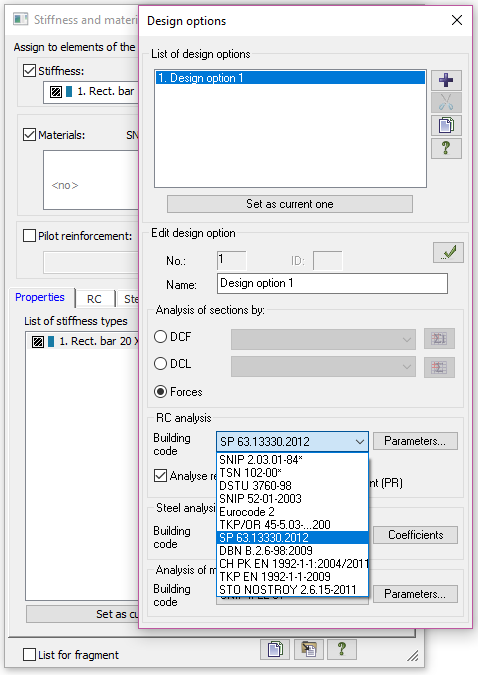
Step 2.
When you define materials for analysis of RC structures, select the 'Account of fire resistance' check box.

Step 3.
To define combustion conditions, click appropriate button ( )
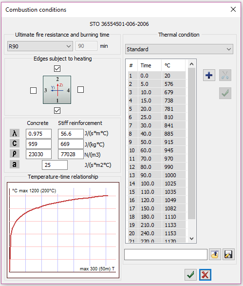
Then in the 'Combustion conditions' dialog box, specify parameters for fire resistance of an element.

In the 'Combustion conditions' dialog box, the following values should be defined:
Ultimate fire resistance
When you select ultimate fire resistance, you automatically define the time during which fire load is acting on the structure. It is possible to define the standard value for ultimate fire resistance or select the 'User-defined' option and input any value manually.

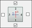
Edges subject to heating
To select sides that will be subject to fire load, just select appropriate check boxes.

Properties of thermal conductivity
There is an option to define the following thermal conductivity properties for concrete and stiff reinforcement (if it is defined in the section):
![]() - heat conductivity coefficient
- heat conductivity coefficient
![]() - heat absorption coefficient
- heat absorption coefficient
![]() - unit weight
- unit weight
![]() - coefficient for convective heat transfer
- coefficient for convective heat transfer
Thermal condition
You could either select one of the standard graphs of fire spreading or indicate a user-defined one. Standard graphs of fire spreading depend on the building code. For STO, only Standard graph is provided, for Eurocode and DBN ' graphs for Standard, Exterior and Hydrocarbon fire.
Step 4.
Analysis results.
|
To display analysis results for fire resistance, on the RC ribbon tab, on the Reinforcement panel, click appropriate button. To display contour plots of temperature, in the 'Information about element' dialog box, on the Fire Resistance tab, select appropriate check box. Then the Fire resistance of an element dialog box (see Fig.7) is displayed on the screen. Use this dialog box to display contour plots of temperature at the time point that was specified with ultimate fire resistance. For example, if the ultimate fire resistance was defined as R90, it means that analysis results will be displayed for distribution of temperature at the 90th minute of combustion. In the new Fire resistance of an element dialog box it is possible to display: 1. Distribution of the temperature along the section. 2. Changes in physical properties of concrete and reinforcement depending on heating temperature in the section, namely ultimate strength in compression / tension and modulus of elasticity. |
Fig.6. 'Information about element' dialog box
|

Fig.7. Contour plots of temperature for beam section (combustion from three sides)
(combustion from three sides)
To display reinforcement that was selected for elements in analysis on fire resistance, on the Results (RC) menu, click Fire Resistance Reinforcement.

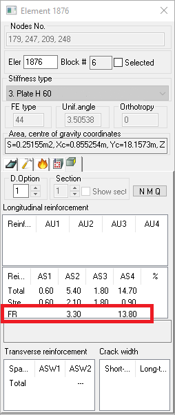
It is also possible to preview the fire resistance reinforcement in the 'Information about element' dialog box. On the last tab in this dialog box Reinforcement FE (see Fig.9) ' reinforcement selected in analysis on fire resistance.

If you find a mistake and want to inform us about it, select the mistake, then hold down the CTRL key and click ENTER.


Comments