Launching LIRA SAPR
After the installation of the LIRA SAPR application on your personal computer, launch it by left mouse double-clicking on the shortcut icon (during the installation keep the path to the Program Files folder as suggested by default C:\Program Files\LIRA SAPR\LIRA SAPR 2020).
If during the installation of the application, the Ribbon view of the interface is selected, then after the initial launch, you will see a toolbar-based workspace. Toolbars have the tabs that display various controls and instruments designed to solve a specific problem. Corresponded to the stages of creating a model, the tabs are the following: create a model, analysis, results visualization, and design. A detailed description can be found in the article:
Directories setting
The directories contain settings, input data, analysis and documentation files, etc.
In the menu Application, in the Settings item's drop-down list, sel ect the command Directories (Fig. 1). LIRA SAPR uses 8 directories. One of them, Base LIRA-FEM Directory, is being set up during the installation and changing of this directory is not allowed for the user. The remaining 7 directories can be changed by the user.
Files of settings ' directory where binary files, which contain settings parameters, are stored.
Files of steel tables ' directory where binary files of steel tables bases are stored.
Input data files ' directory, where binary files of input data are stored.
Text files ' directory where text files of initial data are stored.
Documentation files ' directory where files prepared for documentation are stored.
Files of analysis results ' directory for storing binary and text files of analysis results and temporary files.
Files of temporary results ' directory for storing temporary files generated by the FEM processor.
A new file is saved in Data folder by default C:\Users\Public\Documents\LIRA SAPR\LIRA SAPR 2020\Data, meanwhile, the files generated during the analysis and documentation are stored in the Work directory C:\Users\Public\Documents\LIRA SAPR\LIRA SAPR 2020\Work.

To change the directory, click ''' and indicate the path to new directory or specify the directory manually.
Units of measurement setting
In the Application menu, in the drop-down list Settings , select the command Units of measurement (Fig. 2) and according to the system of units chosen by the analysis specialist (SI or technical, for example, meter'ton'second or MTS), assign the units of measurements of basic units (units settings can be changed at any stage of work with the project).

Creating a new project
To create a new model, click on Application button and fr om drop-down list select New.
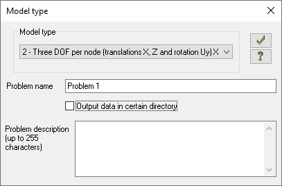
In the dialog box Model type, set the following parameters:
- the name of the new problem - for example, "Problem 1" (the problem code by default is the same as the problem name);
- in the drop-down list, select Model type:
Model type 1 ' models located in the XOZ-plane; each node has 2 degrees of freedom (DOF) ' linear displacements along X, Z or X2, Z2 axes. Plane trusses and wall-beams are analysed with this model type.
Model type 2 ' models located in the XOZ-plane; each node has 3 degrees of freedom (DOF) ' linear displacements along X, Z or X2, Z2 and rotation about Y or Y2. Plane frames are analysed with this model type; elements of trusses and wall-beams may be included.
Model type 3 ' models located in the XOY-plane; each node has 3 degrees of freedom (DOF) ' linear displacements along Z or Z2 and rotations about X, Y or X2, Y2. Beam grillages and slabs are analysed with this model type; account of elastic foundation may be considered.
Model type 4 ' spacial form models where each node has 3 degrees of freedom (DOF) ' linear displacements along X, Y, Z or X2, Y2, Z2. 3D trusses and solids are analysed with this model type.
Model type 5 ' general spacial form models with 6 degrees of freedom (DOF) per node. 3D frame works, shells are analysed with this model type; solids as well as account of elastic foundation may be considered.
Model type 6 ' general spacial form models with 7 degrees of freedom (DOF) per node. Same as in the Type 5, but with one additional degree of freedom W - the deplanation of the bar section.
Model type 15 ' general spacial form models with 1 degree of freedom per node ' temperature t.
After that click on the button OK.

Dialog box Model type dialog box also can be opened with the type selected before. In order to do it, in the menu Application, in the drop-down list New or on the quick access panel in the drop-down list New, select the corresponding model type.
If you find a mistake and want to inform us about it, select the mistake, then hold down the CTRL key and click ENTER.

Comments