Objective
To determine the stress–strain state of a beam on unilateral supports.
Reference
A.V. Perelmuter, V.I. Slivker. Design models of structures and their analysis. Kyiv, Stal, 2002, p.122.
Problem statement
To determine the reactions of unilateral supports or the deflections in the direction of their action.
Design model
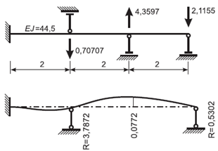
A three‑span beam with one end rigidly fixed and three rigid unilateral supports in compression. The beam is subjected to concentrated forces applied to the supports.
Geometry
Span length L = 2 m
Material properties
The bending stiffness of the bar ЕI = 44,5 tf*m2.
The axial stiffness per unit length of unilateral restraints EF/l = 106 tf/m.
Boundary conditions
Node 1: restrained in all degrees of freedom (DOF) for model type 2.
Node 2: unilateral restraint preventing upward displacement.
Nodes 3 and 4: unilateral restraints preventing downward displacement.
Loads
F2 = 0,70707 tf,
F3 = −4,3597 tf,
F4 = 2,1155 tf.
Note
The problem is solved in 2D formulation (model type 2 – XOZ-plane).
The model is generated with FE type 2 – FE of 2D frame (cantilever) and FE type 261 – 1-node FE of one-way elastic spring (unilateral supports).
Since the nodes of FE type 261 have two degrees of freedom — displacements along the global X and Z-axes, the connection of these elements at the nodes is hinged.
To solve the nonlinear problem, a step‑by‑step process is organised (number of steps = 1, minimum number of iterations = 1000).
Nodes: 13. Elements: 15.
Output data

|
|
|
|
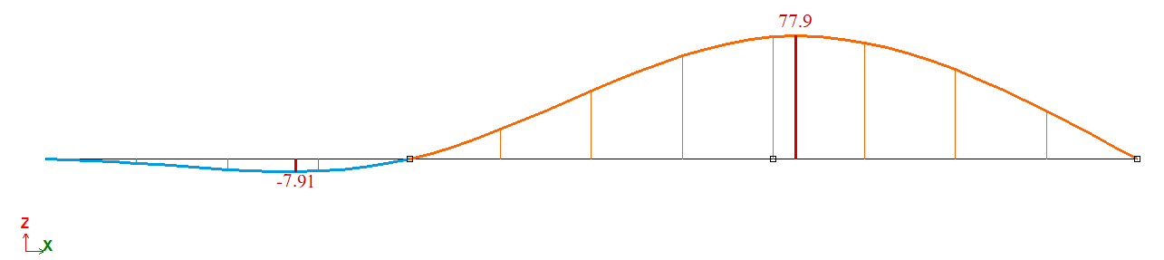
Diagram of displacements
|
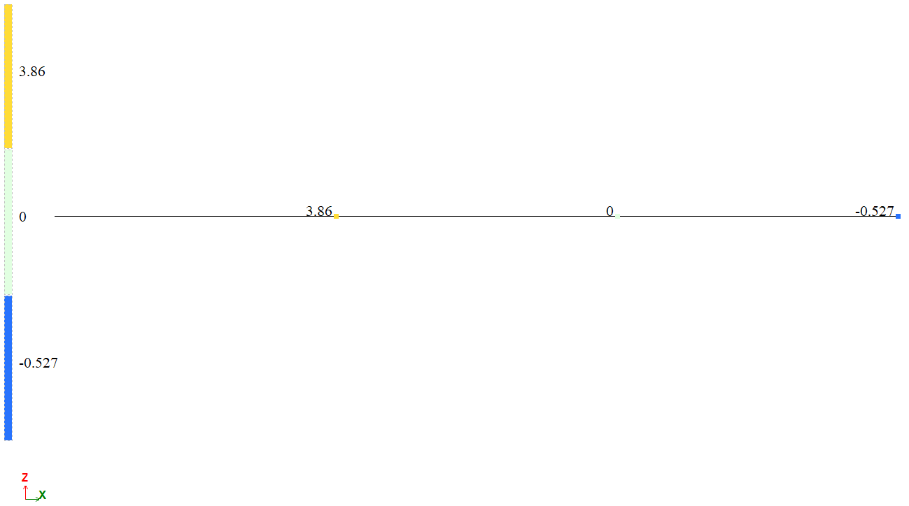
Mosaic plot of forces in the elements of unilateral restraints
|
Comparison of calculation results
| Point | The unknown | Analytical solution | LIRA-FEM | Error, % |
| 3 | w, m | 0,0772 | 0,0779 | 0,92 |
| 2 | R1, t | 3,7872 | 3,8597 | 1,915 |
| 4 | R3, t | -0,5302 | -0,5270 | 0,594 |
Download verification test
If you find a mistake and want to inform us about it, select the mistake, then hold down the CTRL key and click ENTER.
Comments