Objective
To verify the accuracy of determining the displacement at the free end of the bar in the direction of the concentrated load for models of different dimensionality.
Reference
G.Pisarenko, O.Yakovlev, V.Matveev. Strength of materials (Handbook). - Kyiv: Naukova Dumka, 1975.
Problem statement
To determine the displacement w of the free end of the bar in the direction of the concentrated load.
Design model
A cantilever curved bar with a longitudinal axis of circular contour, having the length of a split-ring and a constant rectangular cross‑section along the axis, is subjected at the free end with a transverse concentrated load P.
|
|
|
Initial geometry of analytical model
|

Geometry
Cross-sectional dimensions of the cantilever curved bar b = h = 1,0 m
Central angle corresponding to the arc length of the longitudinal axis of the cantilever curved bar α = 360º
Radius of the arc of the longitudinal axis of the cantilever curved bar R = 0,20 m
Material properties
Modulus of elasticity for bars in the model Е = 1 * 107 kPa
Poisson's ratio ν = 0.0
Loads
Vertical concentrated load P = 1 * 10-3 kN
Note
Design model - model type 5, 6 DOF per node. Two design models are considered:
Bar model - 120 elements of FE type 5; the FE mesh is divided along the length of the longitudinal axis with a step of 3,0º, 121 nodes;
Shell model - 480 eight-node elements of FE type 50; the FE mesh is divided along the length of the longitudinal axis with a step of 3,0º and along the bar height with a step of 0,0025 m, 1689 nodes.
Output data
|
Bar model
|
Shell model
|
|
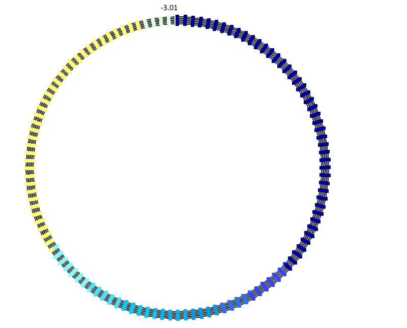
Deformed shape of bar model
|
Deformed shape of shell model
|
|
Displacement w at the free end of the bar in the bar model (mm)
|
Displacement w at the free end of the bar in the shell model (mm)
|


")
Comparison of calculation results
| Model | Displacement w, mm | Error, % |
| Bar | -3,014 | 0.06 |
| Shell | -3,01 | 0.2 |
| Analytical solution | -3,016 | - |
Download verification test
If you find a mistake and want to inform us about it, select the mistake, then hold down the CTRL key and click ENTER.
Comments