- Discretization
- Initially, all objects of structural mechanics represent a continuous environment. As a rule, it is not possible to determine SSS parameters (displacements, stresses, forces) in all points of a continuous environment, since the number of these points is generally infinite. All numerical methods are based on the assignment of a finite number of points at which the desired SSS parameters are located. Replacement of an infinite number of points of a continuous environment by a finite number of points (nodes) is called discretization.
- Triangulation
- The continuous environment is replaced by a set of subareas (triangular, quadrangular, tetrahedron, parallelepiped, etc.) with assigned nodes at their vertices. Thus, the continuous environment is replaced by a discrete environment consisting of individual subareas. Such replacement is called TRIANGULATION (TRIANGULATION - fr om Latin triangulus triangle - determining the mutual location of points on a surface by means of constructing a network of triangles).
The construction of finite element meshes is an important stage of solving the problem of determining the SSS of structures. This stage is associated with satisfaction of a number of contradictory requirements.
On the one hand, a sufficiently dense mesh allows to achieve the required accuracy of the problem solution. On the other hand, an excessively dense mesh increases the time of the problem solution and can lead to poor conditioning of the matrix of canonical FEM equations, and, consequently, to large errors in the factorization of this matrix.

|
|
Mesh | |||||
| 4'4 | 8'8 | 16'16 | 32'32 | 64'64 | Benchmark | |
| Displacements at point B for the full shell wB, ' | -3.357*10-2 | -3.561*10-2 | -3.644*10-2 | -3.657*10-2 | -3.663*10-2 | -3.70*10-2 |
| Error, % | 9.243 | 3.757 | 1.514 | 1.162 | 1.000 | - |
An important factor is the shape of the finite elements. Thus, quadrilateral finite elements are more accurate than triangular finite elements. Equilateral finite elements are more preferable to elements with strongly unequal sides. The last ones worsen the conditionality of the matrix of canonical FEM equations, therefore, equilateral finite elements should be preferred for triangulation.

| Regular mesh | Irregular mesh | |||||
| 4'4 | 8'8 | 16'16 | 32'32 | 64'64 | Benchmark | |
| w '106, ' | 12.271 | 11.813 | 11.664 | 10.679 | 11.295 | 11.512 |
| wbenchmark '106, ' | 11.60 | 11.60 | 11.60 | 11.60 | 11.60 | 11.60 |
| Error, % | 5.78 | 1.84 | 0.55 | 7.94 | 2.63 | 0.76 |
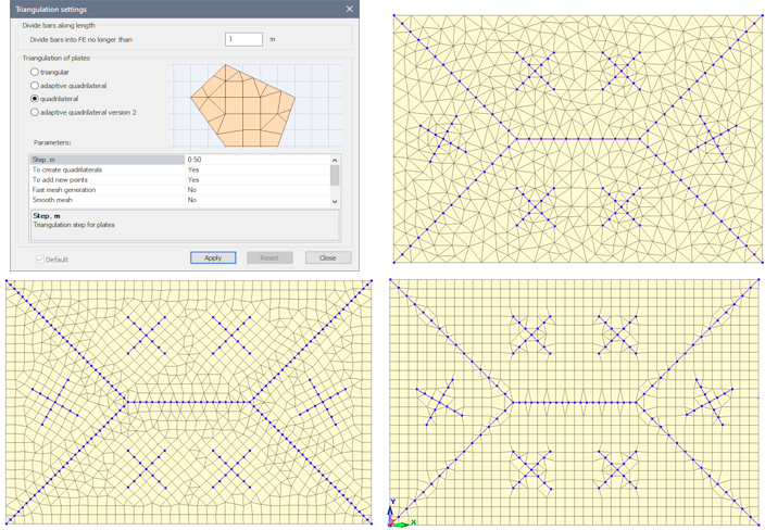
Triangulation methods in LIRA-SAPR
Three triangulation methods are used in LIRA-FEM software
- a method based on the application of triangular finite elements (triangular triangulation). For 3D models, the analogs of these elements are tetrahedrons and triangular prisms;
- a method based on the maximum possible inclusion of rectangular and quadrangular FEs in the finite element mesh (quadrangular triangulation);
- a method based on the organization of regular inclusions in places of stress or force concentration (adaptive quadrilateral triangulation).
For 3D models, the analog of quadrilateral elements is parallelepipeds and octagonal 3D FEs.
The following information is used as input data for realization of triangulation methods in LIRA-FEM software:
- The outer contour of the physical area to be partitioned;
- Information about the required finite element step with possible densification regions;
- An array of internal contours (holes or voids in the triangulated region);
- An array of additional points (coordinates of nodes that must be present in the resulting finite element mesh);
- An array of additional segments (segments with which the edges of the finite elements must not intersect).
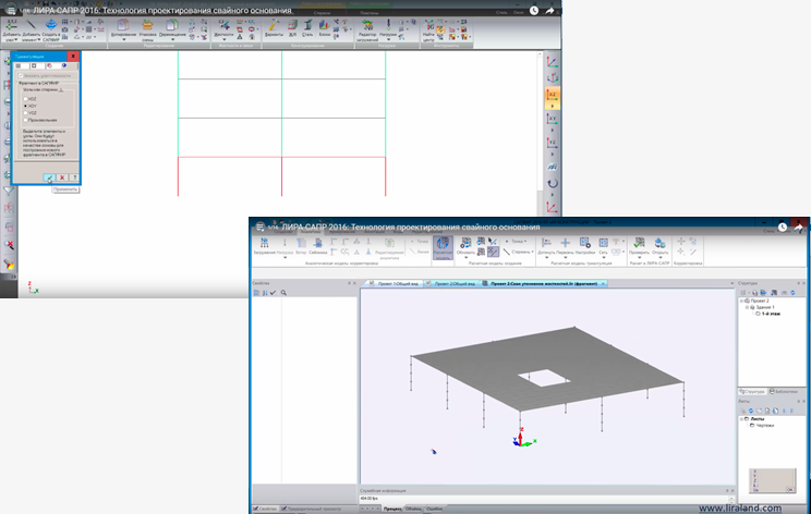
Creating a consistent finite element mesh in LIRA-FEM can be done in three ways (or a combination of them):
- contours triangulation by one of the automatic methods (simple contour, contour with openings, contour editor, fragment in SAPFIR);
- by sequentially entering firstly the nodes of the elements of the design model, and then by displaying the elements themselves (element input);
- using regular fragments to create the geometry of the design model.
There is a rough estimate of the loss of accuracy during rounding: the number of decimal places that are lost as a result of Gaussian factorization of the matrix r=lg10·, where · is the size of the matrix of canonical equations. 'Thus, if the initial values of the matrix are made with double precision (approximately 15 decimal places), the result will contain 15-r correct signs.
As a purely engineering recommendation, it may be advisable to assign the triangulation step such that the most characteristic span contains at least 10 triangulation nodes.
If you find a mistake and want to inform us about it, select the mistake, then hold down the CTRL key and click ENTER.


Comments