In LIRA SAPR, a command Information about nodes and elements can be found on the Select toolbar. It allows not only to get the full information about all components of the model but also to edit many of them. To run it, click the button ![]() - Information about nodes and elements and point the cursor onto any element or node. Depending on the commands that are run, the appearance of the mouse cursor within the model display window may vary. In the node or element assignment mode, to get the information the cursor looks like this -
- Information about nodes and elements and point the cursor onto any element or node. Depending on the commands that are run, the appearance of the mouse cursor within the model display window may vary. In the node or element assignment mode, to get the information the cursor looks like this - ![]() . The command is active until the user will cancel it by clicking the button
. The command is active until the user will cancel it by clicking the button ![]() - Information about nodes and elements or will activate another mode on the Select toolbar. It means that the user can get an unlimited amount of information opening a new dialog boxes by clicking from one node (or bar) to another.
- Information about nodes and elements or will activate another mode on the Select toolbar. It means that the user can get an unlimited amount of information opening a new dialog boxes by clicking from one node (or bar) to another.
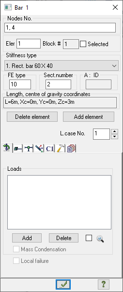
The Information about element dialog box is shown in Fig. 1.


The dialog box provides full information about the properties of the selected node or element. Depending on the mode (creating a model, analysis results visualization, and design), the dialog box Information about element may contain various information.
More details
The dialog box Information about element in mode of creating design model contains:
- element’s No.;
- No. of its nodes on the model;
- check box to select the element on the model;
- No. of block where the element is included;
- stiffness type;
- FE type;
- number of sections (for bar) in which forces are calculated or unification angle of local axes for plates and solids;
- rotation angle for orthotropy axes (for plates and solids);
- length (area, volume) and coordinates of gravity centre of an element in global coordinate system;
- spin box with load case numbers.
In the mode of analysis results visualization:
- element’s No.;
- No. of its nodes on the model;
- check box to select the element on the model;
- No. of block where the element is included;
- stiffness type;
- FE type;
- number of sections (for bar) in which forces are calculated or unification angle of local axes for plates and solids;
- rotation angle for orthotropy axes (for plates and solids);
- length (area, volume) and coordinates of gravity centre of an element in global coordinate system;
- spin box with No. of load cases or DCL;
- spin box with No. of sections for bars.
In the mode of Reinforced concrete (RC) and steel structures:
- element’s No.;
- No. of its nodes on the model;
- check box to select the element on the model;
- No. of block where the element is included;
- stiffness type;
- FE type;
- number of sections (for bar) in which forces are calculated or unification angle of local axes for plates and solids;
- rotation angle for orthotropy axes (for plates and solids);
- length (area, volume) and coordinates of gravity centre of an element in global coordinate system;
- spin box with No. of load cases or DCL;
- spin box with No. of sections for bars.
Information dialog boxes also provide the possibility to correct the data. Components such as stiffness, loads, hinges can be changed without leaving the window.
Therefore, to correct the load, you need to perform the following operations:
- in the spin box with No. of load cases by scrolling the list, and select the desired load case;
- select the load from the list by a double click;
- in the dialog box that appeared (Fig. 2), set new load parameters to the corresponding fields;
- close the dialog box “Load Parameters” by clicking the “OK” button;
- close the dialog box “Information” by clicking the “Apply” button.


It is possible to correct any of the parameters characterizing a given type of load. But it is impossible to change the type of load. If you need to do this, click on the button Delete to cancel assigned load (Fig.1). Then reassign load with desired type (Loads button, Loads panel, Create and edit tab).
The “Information about node” dialog box (Fig. 3) looks like the “Information about element” dialog box. In this dialog box you can correct the loads applied to the node and set restrains or correct existing ones (check/uncheck direction of restrains and click Apply).
In dialog box Information about node/element there is an opportunity to delete selected node or element. The Delete element/node button is used to delete an element or node (and, consequently, elements adjacent to it).
After clicking the Delete button you don’t need to click on the Apply button. To restore the lost part, you will need to use the - Cancel command (Quick Access Toolbar). ![]() - Cancel command (Quick Access Toolbar).
- Cancel command (Quick Access Toolbar).
If you find a mistake and want to inform us about it, select the mistake, then hold down the CTRL key and click ENTER.
Comments