How to apply Tekla-Structures program to prepare LIRA-FEM design model
In Tekla Structures it is possible to generate analysis model that includes bars, plates, loads and boundary conditions.
LIRA-FEM program supports two-way integration with Tekla Structures. The Tekla Structures analysis model may be directly transferred to VISOR-SAPR module. Bars, plates, hinges, restraints and loads may be transferred. In this way, steel frames may be successfully transferred for analysis. When all necessary data is added in LIRA-FEM program, you could carry out static & dynamic analyses, check/select sections of steel elements and transfer them back to Tekla Structures. Such technology is shown in Fig.1.<
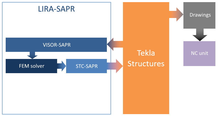
In complex cases, when the structure includes reinforced concrete (RC) elements, it is recommended to transfer data to SAPFIR module (preprocessor) and generate the FE model there. This approach will enable the user to control the quality of FE meshes and use the actual dimensions of RC elements (formwork) for further arrangement of rebars in Design of RC structures module.

In this case, when the structure is analysed, reinforcement is selected and arranged in Design of RC structures module, analysis results may be exported to Tekla Structures where it is possible to obtain RC, steel and detailed drawings. A distinctive feature of the Tekla program is the generation of data for numerical control (N/C) machine. This approach is shown in Fig.2.
Let's consider each stage in the approach in more detail.
Export of the model
When LIRA-FEM program is installed, the export/import menu is integrated into Tekla Structures. To export a model from Tekla Structures, you should generate analysis model in Tekla Structures. To do this, select the 'Analysis & design models' command (see Fig.3). Then the 'Analysis & design models' dialog box is displayed (see Fig.4).

In this dialog box, in the 'Create' area, click 'New'. Then settings for analysis model will become available (see Fig.4).

Then, in the 'Analysis application' box, select LiraXX_Tekla_XXXX, where XX and XXXX are the versions of LIRA-FEM and Tekla Structures.
When analysis model is generated in Tekla Structures, it is necessary to notice its content and the interpretation of the physical objects in the model. For example, the foundation element does not have an analysis representation in Tekla model and is not generated in analysis model. For models that have detailed design model, it is necessary to use filters during generation of analysis model in order to exclude minor elements.
Tekla Structures analysis model should not include bolts, welds, elements of steel joints. If steel joints are already modelled in Tekla Structures, in the 'Use rigid links' row, select 'Disabled', 'Member axis location': default. Then bolts and welds will be excluded from the Tekla Structures analysis model.
In the 'Curved beams' box, select 'Split into straight elements'.
In the 'Consider twin profiles' box, select 'Disabled'.
Then press 'OK'. Tekla Structures will generate the analysis model. Name of generated analysis model will appear in the 'Analysis & design models' dialog box (see Fig.5). When you select this row, the buttons in the 'Analysis application interface' area will become available.
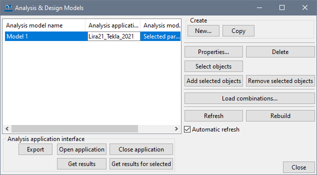
Click 'Export' and follow instructions in Tekla Structures. Then, the export model dialog box will appear (see Fig.6).
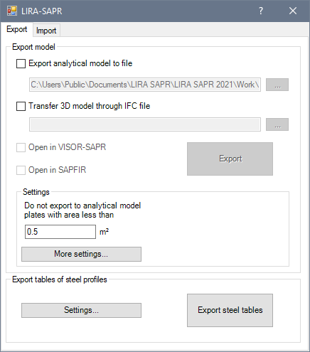
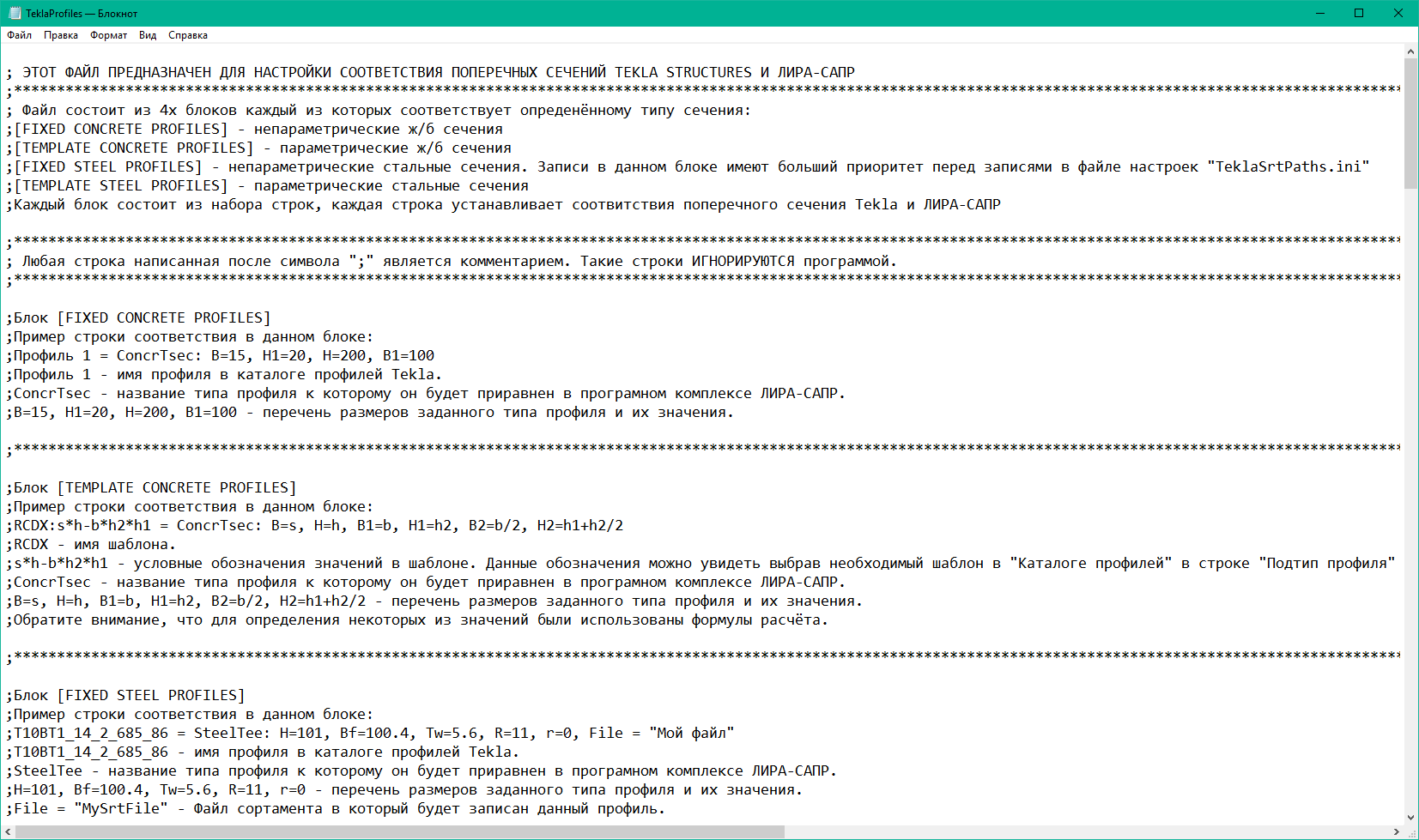
Steel tables available in Tekla Structures may be automatically exported and applied in LIRA-FEM analyses (see Fig. 6). When steel tables are exported, the table of correspondence between the Tekla Structures and LIRA-FEM profiles is used. By default, the TeklaProfiles.ini file for profile correspondence is located at C:\Users\Public\Documents\LIRA SAPR\LIRA SAPR 20XX\Settings. The TeklaSrtPaths.ini file for steel profile correspondence is also located there (see Fig.7). The table shows the LIRA-FEM profile that the Tekla Structures profile corresponds to. The table is provided with LIRA-FEM program. It is possible to edit the table manually.
When the steel tables are successfully exported, it is possible to export Tekla Structures models to LIRA-FEM program. It is possible to preview and edit the exported steel tables in the Steel Rolled Shapes (SRS-SAPR) module (Editable steel tables) (see Fig.8).
Tekla non-standard section types described as stiffnesses from Cross-section Design Toolkit module are also transferred to the LIRA-FEM design model.
In the settings for model export, you can specify the size of plates that will be exported (to exclude from the model embedded items and other plates with small area).
To export the Tekla analysis model to a file, specify the path and name of the file where it should be exported.
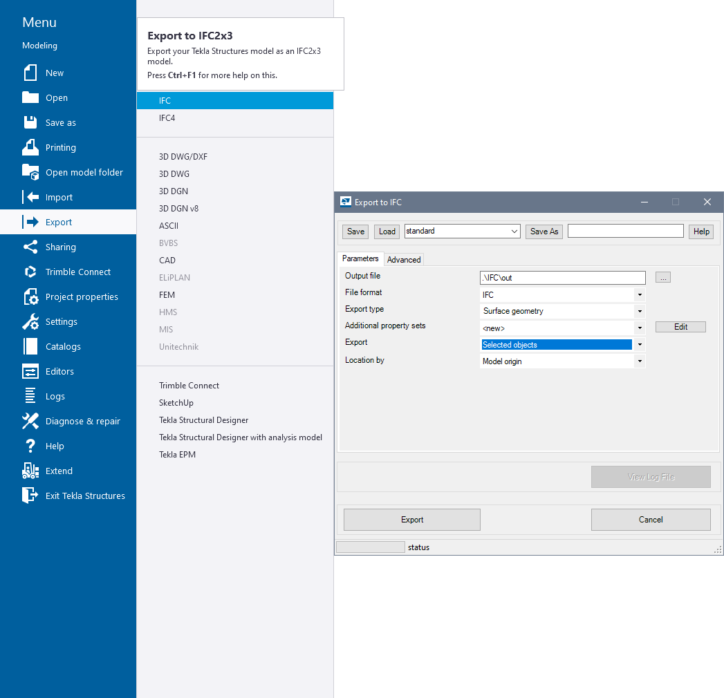
To export 3D model, specify previously created IFC file obtained for this model. To generate this file, on the Tekla Structures menu, point to 'Export' and select 'IFC' item (see Fig.9).
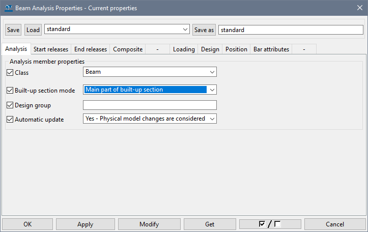
To export welded I-beams, model them with three beams or columns with rectangular sections.

Then, in the Tekla analysis model in the properties of one of the bars (that will become the main one), in the 'Built-up section mode' option, select the 'Main part of built-up section' (see Fig.10). Twin profiles will be transferred correctly only if the rotation angle of both elements in such profile is the same.
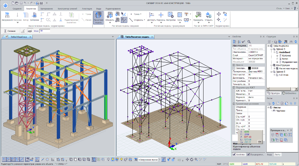
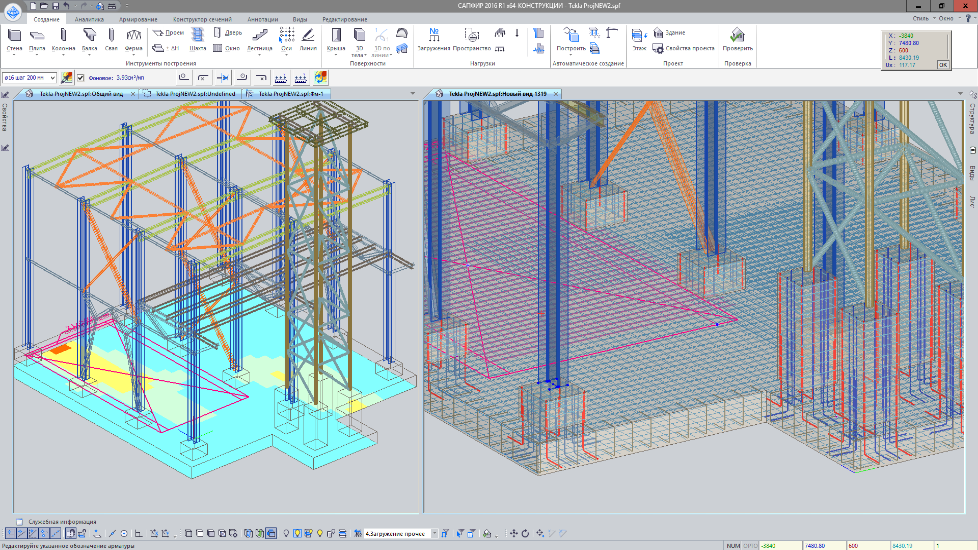
3D SAPFIR model (architectural model with actual dimensions) is generated from the Tekla Structures design model while the meshed model of SAPFIR-Structures is generated from the Tekla Structures analysis model in order to obtain a high-quality FEM. Thus, the actual dimensions of the structure (for formwork, for example) are exported together with additional data for the Tekla analysis model (simplifications / transformations of the analysis model made in Tekla Structures, specified material properties, boundary conditions and loads) (see Fig.11).
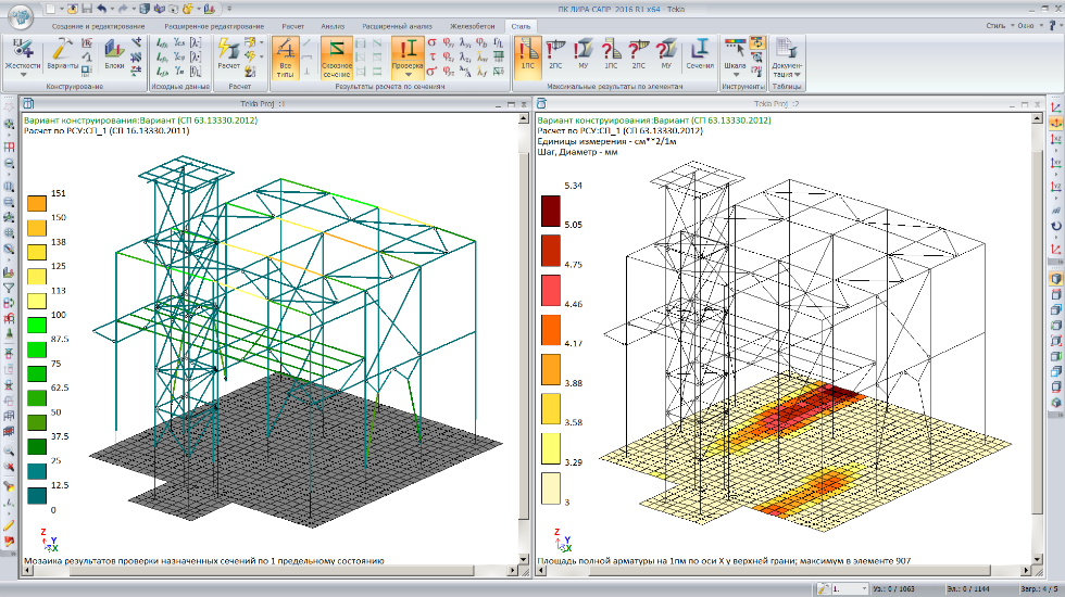
After analysis, updated cross-sections of bars and plate thicknesses are transferred from LIRA-FEM to Tekla Structures. During the work in LIRA-SAPR, the cross-sections of elements may be modified either by the program or by the user (selection of optimal steel sections according to obtained forces; modifications in RC sections because of the failure to meet the requirements for strength, stiffness or inability to arrange selected reinforcement) (see Fig.12).
Reinforcement selected for RC elements (as contour plots for plates and required reinforcement in every design section of bar) may be transferred to the Design of RC structures module, where the reinforcement will be arranged in the formwork in a semi-automatic mode. Then, designed RC structure may be transferred to Tekla Structures.
Import of the model
During import procedure, the cross-sections of bars in Tekla Structures model will be replaced with the cross-sections of the most suitable bars in LIRA-FEM model. The bar is considered the most suitable if its axis is the closest to the bar axis (in Tekla Structures analysis model) in the specified neighbourhood. The bar is not the most suitable if the angle between the bar axis in LIRA-FEM and the bar axis in Tekla Structures is greater than the specified angular accuracy (angle of deviation).
In addition to updating the bar cross-sections, import from LIRA-FEM software allows the user to update the thickness of walls and slabs in Tekla Structures, as well as automatically generate their reinforcement pattern based on reinforcement model in Design of RC structures module. The thickness of the walls and slabs in Tekla Structures is considered to be equal to the thickness of the most suitable walls and slabs in Design of RC structures module. The wall or slab is considered the most suitable if its analytical contour is the closest to the contour of plate analysis model in Tekla Structures in the given neighbourhood. The contour is not the most suitable if the angle between the contour plane in Design of RC structures and the contour plane in Tekla Structures analysis model is greater than the specified angular accuracy (angle of deviation).
To import data from LIRA-FEM and Design of RC structures, either open the 'Import' tab (see Fig.13) in the LIRA-FEM dialog box (see Fig.6) or click the 'Get results' in the 'Analysis & Design Models' dialog box (see Fig.5).

The settings for the import procedure include the neighbourhood and angular accuracy (angle of deviation) that will be applied to search for the most suitable bars in LIRA-FEM and walls/slabs in Design of RC structures module.
To import cross-sections of steel and RC bar elements, select the analysed LIRA-FEM file (file with *.lir extension) and design option.
To update plate thicknesses and import their reinforcement pattern, specify the path to the Design of RC structures model (file with *.spf extension), where the reinforcement pattern was generated. It is also possible to specify an XML file exported from Design of RC structures module with the 'export of reinforcement for Tekla Structures' option (see Fig.14).
If you find a mistake and want to inform us about it, select the mistake, then hold down the CTRL key and click ENTER.

Comments